Lab 2
Introduction
This week the iCE40 UP5K FPGA was programmed to drive two seven segment desplays simultaneously using only one seven-segment decoder HDL Module which requried time-multiplexing. In order to do so the signals were oscillating at a fast enough speed that the viewere would not notice any flickering. The two displays were controlled using a DIP switch for each display one on the breadboard and on on the FPGA dev board. The sum of both hex inputs was then displayed in binary using 5 LEDs on the breadboard.
Design and Testing Methodology
This labs design was encoded in HDL on Lattices using system verilog to accurately encode desired circuit behaviors and then uploaded to the FPGA. The verilog was verified using a testbench for each module that tested all possible inputs and proved that the desired outputs were obtained. The external 7-segment displays and 5 LEDS were then wired on a breadboard and tested to confirm compenents performed in the desired manner. ## Technial Documentation Github repository containing all code used for this lab: https://github.com/lanilei/E155labs/tree/main/lab2/FPGA
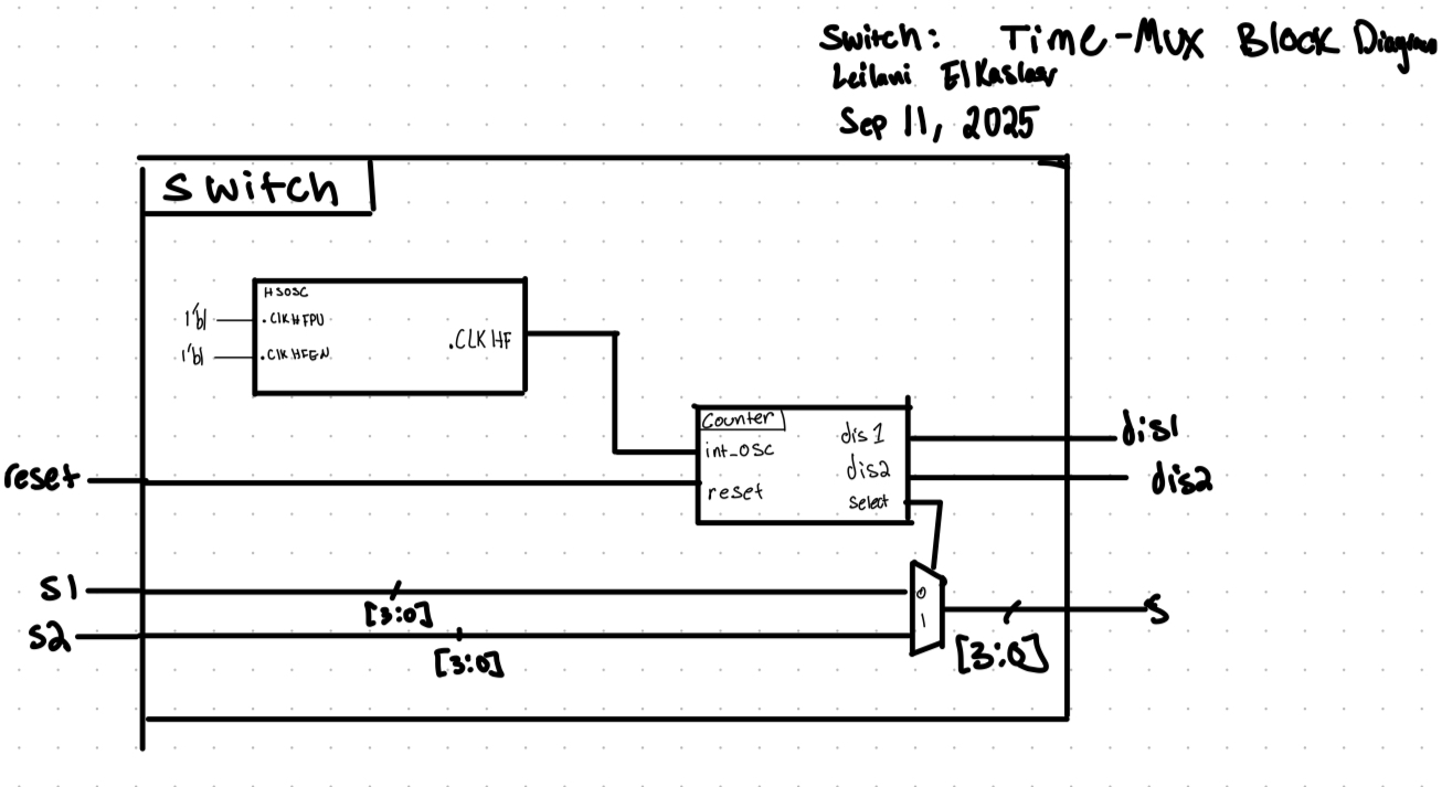
Block Diagram
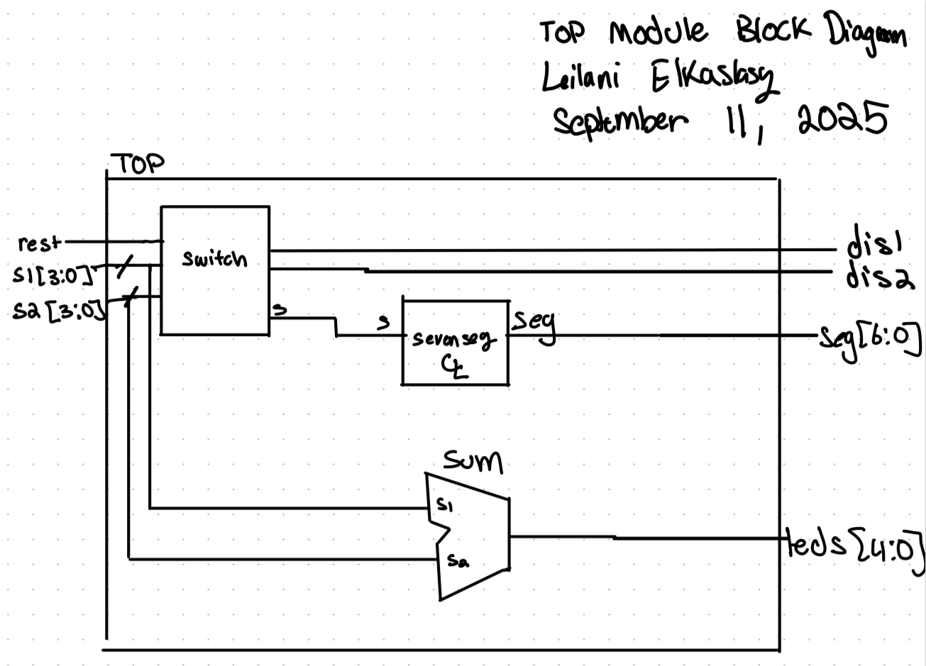 In order to approach solving this problem, each function was seperated into its own module. The LEDs were combined to be driven by LED.SV and the Seven segment display was controlled using combinational logic in its own module. These two modules were tied together using a top module that called upon them both.
Calculations

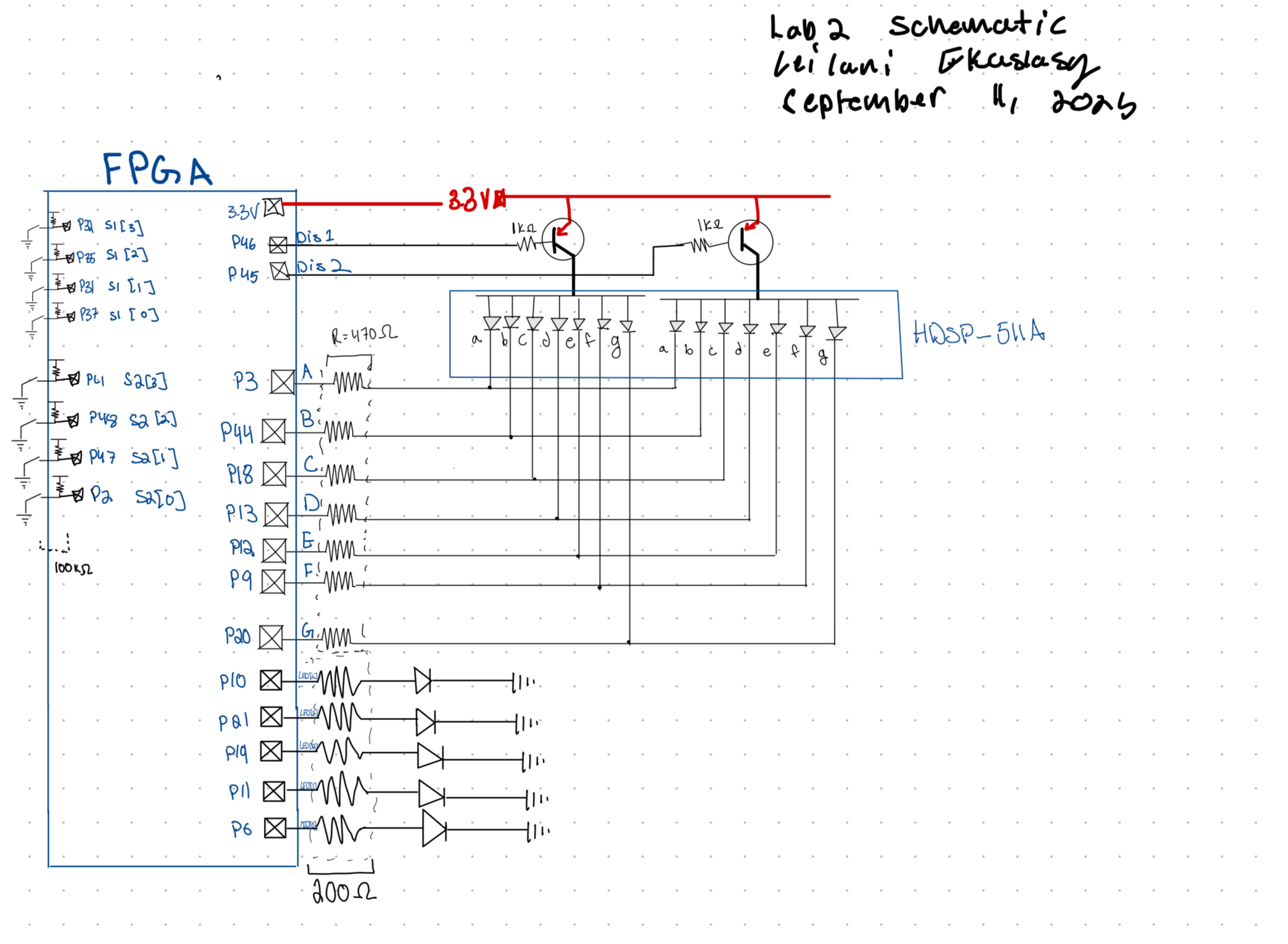
Schematic
Using the resistor value confirmed by the above calculations a circuit was created on a breadboard in accordance with the following schematic:
Results and Discussion
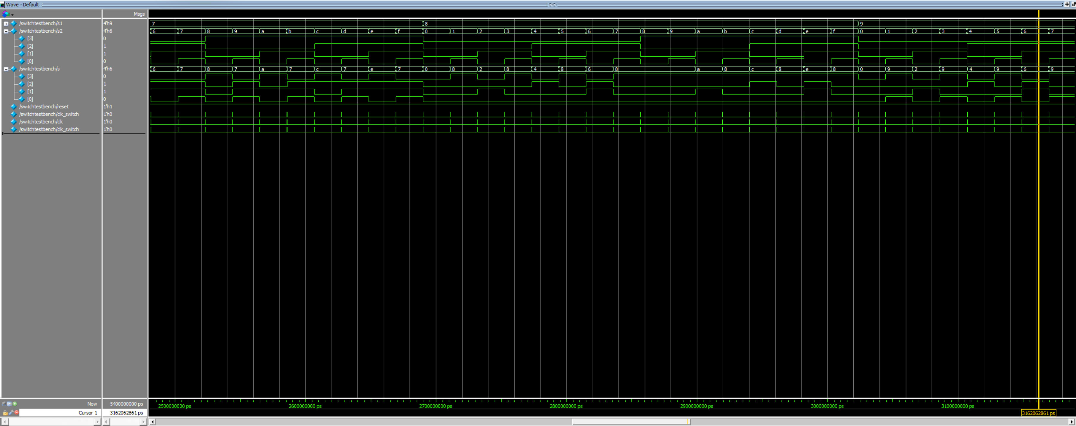
Both the simulated and physical circuit were tested extensively confirming all desired functionality. Both seven segment displays showed all possible digits of hex in accordance with the input switches s1[3:0] and s2[3:0]. 5 LEDs showed the sum of s1 and s2.
Testing
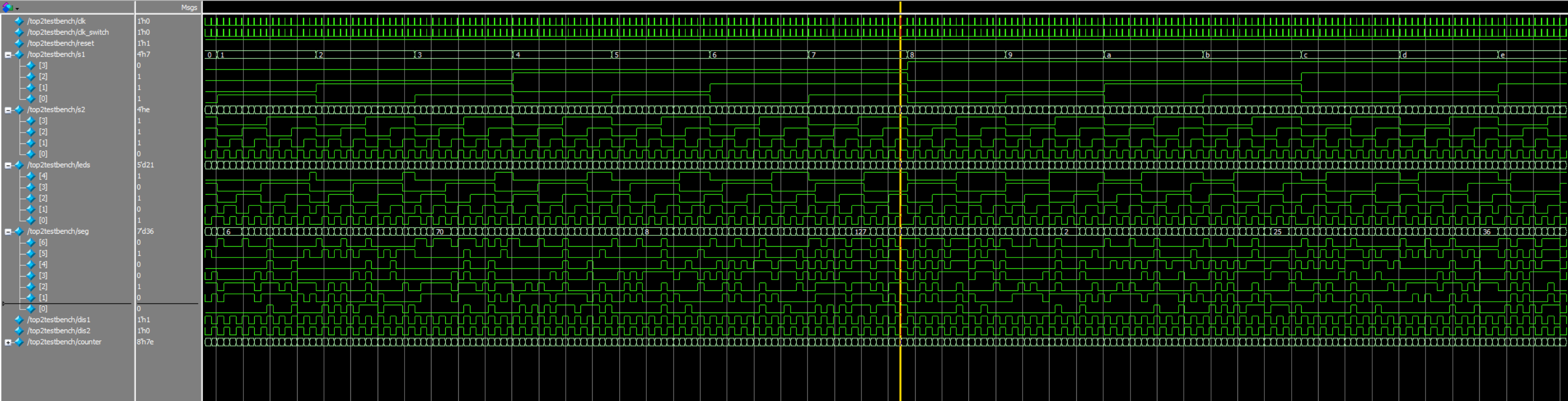
Testbenches
The system verilog modules were tested individually using a simulated testbench. All Modules were confirmed to work as expected.

Physical Circuit testing
The FPGA Dev Board and bread board circuit were all tested extensively in the lab by ensuring the input switches, LEDs, and seven segment display worked as expected. 
Conclusion
This lab took 36 hours. Through breadboarding, programming, and debugging a multiplexed dual seven segment display was fully realized along with a 5 LED array to display the sum of both dip swithc inputs.
AI Results Summary
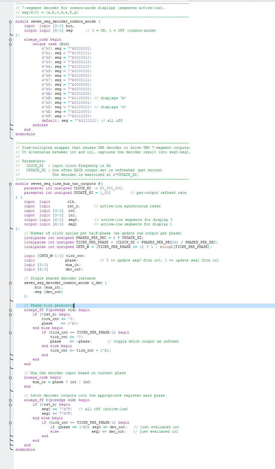 The AI generated system verilog was interesting. I would not have thought to use local param integer command for the counter. The most useful part of the experience of prompting AI was the immediate generation of a full module. However, it did not include enough detail for me to understand the details of its implementation.

Chat GPT was promted to “Write SystemVerilog HDL to time multiplex a single seven segment decoder (that decodes from four bits to a common anode seven segment display) to decode two sets of input bits and drive two sets of seven output bits.” Within seconds it generated the code shown in Figure 9. When uploaded to a new Radiant project it compiled immeadiately. This means that the output was of good quality since there were no bugs preventing it from synthisizing. It also was able to put the verilog together far more efficiently than the time it took me to write manually.
Some new syntax that was familar but not used much in the past was that it declared variables as unsigned when in the past I had just declared variables. The formatting was really clean and the comments were clear something I will aim for in my next projects.
Chat GPT was then prompted to “Write SystemVerilog HDL to time multiplex a single seven segment decoder (that decodes from four bits to a common anode seven segment display) to decode two sets of input bits and drive two sets of seven output bits. Use the seven segment decoder and oscillator provided in the attached files.”
This also took a matter of seconds after uploading the files. It also synthesized on the first try in Radiant. This means the code was not significantly buggy and therefore High Quality.
Next time an LLM is used in my workflow I might call upon refrence files of my own since that seemed to create a more reliablw result.